Rising From The Ashes
Resurrecting the Orca in the form of my new Xfly X1500
Orca’s End
Last weekend, my trusty Orca met its fate on what was meant to be a routine flight. After tens of hours of perfect autonomous flying, the aircraft pitched down in FBWA and wouldn’t level off despite adding full back stick, ending with a heavy impact into the ground and the aircraft being written off.
 Orca after the terminal manoeuvre
The cause of this uncommanded pitch down was easily found from a log inspection. The compass calibration seemed to become corrupted during flight, leading to a severe mag disagreement between GPS ground track and compass reading - up to 170 degrees difference at worst. This resulted in the EKF attitude estimation diverging significantly from reality. At approximately 111 seconds into flight, the attitude reference returns to using EKF3, but at this point the pitch estimation rapidly increases from the actual value, estimating over 40 degrees more nose-up than reality after only 2 seconds. This divergence only increased until the crash, finishing with a deviation of over 80 degrees more positive than the actual pitch. This meant that the attitude controller demanded nose-down elevator to compensate and bring the EK3 estimation back to level, but as the estimation was so high, full nose down elevator output was maintained for the entire dive even with full nose-up input from the transmitter, due to the perceived pitch error.
 EK3 pitch estimation divergence compared to DCM and GPS track
 EK3 heading estimation against DCM and GPS track
As for exactly how this happened, it’s not clear. There are no mag error messages in the log and the vehicle armed successfully - unfortunately the compass check bit in ARMING_CHECK was disabled. My GCS laptop was refusing to connect to mLRS so I went without and therefore only had the Yaapu readout of heading to tell that the pre-takeoff heading was incorrect. Had the map on the GCS been working it’s possible I would have spotted this inconsistency. Digging into the parameter file, the compass offset vector values are troubling. The X and Z values were well over 1000 mG, and the ArduPilot documentation suggests these values should ideally be zero and anything over 600 mG will trigger a compass calibration failure. This suggests that something had affected the compass calibration before this flight, but exactly what caused this cannot be known.
After impact, the wings were intact and the tail repairable, but the fuselage was totally destroyed and unfortunately the model isn’t manufactured anymore. I looked for a new model with the intention of re-using the electronics as far as possible, and quickly landed on the Xfly-Model X1500. This is a similar twin, designed for long range FPV, with a slightly higher wingspan and aspect ratio. It’s designed specifically to fit a 4S2P 21700 Li-Ion battery which is my go-to long endurance pack, so I bought a kit and got to work transplanting the electronics.
X1500 Kit Build
The kit arrived on Tuesday and I rushed the assembly to be ready to maiden it on the weekend, so there are a few compromises made which will be fixed later. The foam parts arrived already glued together, with wiring installed and the control surface horns set for the included control rods to be installed. There are a few small build quality details I don’t particularly like, but I can give Xfly a pass on a kit that costs less than £135. All plastic parts are 3D printed, which is fine but has resulted in one part breaking from incorrect print orientation already. It does mean the parts can be reprinted easily, should Xfly choose to send the original models which they were happy to do. It looks like the foam flashing has been removed a bit haphazardly on some parts, leading to some small panel gaps if you look closely. The covers for the wing root electronics compartment are comically thin, with an inexplicable slot cut in them, so I have simply taped over the entire part for now. I will note there are some features I do like, such as the cable routing channels down the side of the fuselage which help hide wiring.
The wings attach by a neat 3D printed latching system, and there are blind fit connectors between the wings and fuselage for quick installation. The two fuselage canopy latches use a similar latching system which seems to work well. On the wing side, the power terminates in an XT60 ready for ESC connection, and there are latching servo connectors for the ailerons and throttle. The wings include red/green LEDs on the wingtips, and these are terminated with a two pin servo connector. I started with the wings, where I immediately realised there was no consideration for the installation of custom motors. Nevertheless, I made up a quick set of motor mounts similar to the Orca and attached the motors. The ESCs just about fit through the motor mount foam and into the wing, despite the bottom part of the motor mount foam already being glued together. The included cowlings also did not fit to my motors, being too long, but an email to Xfly and quick response got me the orignal STLs, from which I was able to reverse engineer a shorter version to fit my motors. I printed them out in yellow to match the colourful nose. I installed my aileron servos and spliced the LED power into the connector. I’m re-using my Corona DS-919MG servos and they require just a little foam removal to fit in the moulded servo slots.
 Stock cowlings were too long for my motor install
 Included wing connectors
On the fuselage side, I completely remade the wiring looms. Partly this was due to the ailerons and throttles being y-leaded by default which is not useful for my setup, partly so that I can take a connector apart to check the factory soldering quality, and partly so I can use some Powerbox wire to keep things looking clean! Removing heatshrink form the wing connector showed decent solder joint quality - although the amount of solder in the main power pins is sparing, the joint is fully wetted and good enough for this application. The connector is pinned out from the factory with the throttle and aileron PWMs charing power and ground, with separate signals. I used the spare pin as a second ground to keep the throttle and aileron separate. The tail setup leaves a little to be desired. Xfly have included a ‘panel-mounted’ servo connector on the tail and a way to do this for the tailplane side also, but my servo housings didn’t seem to fit into the panel mount at all. I had to remove them and ended up with standard servo connectors, which makes tail assembly a bit clumsier.
 Solder joints on connector from the factory
 All control output harnesses installed
I re-used the Matek F405 Wing autopilot and power wires, and went with a basic install with one eye on swapping this out for a H743 board in the near future. With the control surface and throttle outputs wired up, I added the external sensors. There is a GPS mounting inset on the lid of the payload bay, but I don’t want to worry about damaging the wires when removing it, so I opted to install the GPS on the top of the fuselage behind the flight controller similar to on my Orca. The airspeed sensor and mLRS receiver fit into the payload space, with the intention to better place the receiver and antenna in the future. The X1500 has clearly been designed for a basic FPV install and not much else in terms of payload carrying or modularity, as the flight controller mount is a solid block of foam taking up a lot of space and there is no access to the internals of the rear fuselage for installation of sensors on the rear. My VAS antenna didn’t survive the Orca crash so I used an old stock mLRS 868 MHz antenna, and had to poke it out the top of the vehicle to make it fit.
 The 4S2P 21700 pack fits perfectly in the nose
 Ready for the maiden flight
The kit comes in a sturdy and well organised box which I’ve kept for transportation, cutting away at parts of the foam so that the aircraft can still fit in with the sensors and props attached. All up with my 4S2P 21700 pack (576 grams), the X1500 weighs in at 2.026 kg. With the battery right in the nose, the CG is at the front of the wing harness access hatch - about 70 mm behind the root LE. The manual suggests 55 mm, but I flew the maiden with this CG instead. I estimated the MAC to be about 200 mm (considering the minor taper with a root chord of 220 mm), so a CG at 35% MAC seemed OK. The only snag I didn’t solve before the maiden was the control surface deflections. The existing horn holes distances limited the aileron and elevator but I gave each surface symmetric deflections and will fix this in the future to increase throws. The elevator servos are generic 9 gram servos, not the DS919-MGs, and I have ordered some to replace these.
| Surface | Manual (High Rates) /mm | Actual /mm |
|---|---|---|
| Aileron | ±18 | ±15 |
| Elevator | ±15 | ±10 |
| Rudder | ±17 | ±17 |
I left the ArduPlane parameters mostly as they were, only updating the servo outputs, adding an additional GPS, and including compass in the arming checks (or more accurately, excluding it from the updated ARMING_SKIPCHK). I left the inner loop tune values alone, as the vehicle is very similar to the Orca in shape and size so I expected the tune to perform safely enough. Once I have replaced the elevator servos and updated the throws, I will retune the vehicle.
I’ve christened the model as the Phoenix, respecting the electronic components which have risen from the grave of the Orca to fly again. It’s a bit more catchy than the X1500 anyway.
Maiden Flight
Arriving at the flying field was quite a disappointment, as the wind was blowing strongly and with some noticeable gusts. Still, it’s now a long drive to not fly, so I prepared the aircraft and double-checked my compass calibration. Soon I was in the air, and the aircraft handles very easily in Manual, with a bit of nose-up elevator required to hold level even at my ‘rearwards’ CG, so perhaps this can be moved further back in the future. I very quickly changed into FBWA due to the gusty conditions, and the tune proved acceptable straight away, with the same docile but tight roll characteristics as the Orca. The pitch response felt a bit sluggish which I attribute to the low elevator deflections and the temporary elevator servos having noticeably slow movement, even in Manual. I expect this response to clear up once the new servos are installed.
The inner loop data supports this, with commanded against measured attitudes showing some significant phase lag but no tendency to overshoot and good steady-state behaviour, with perhaps a little more integrator term needed to eliminate the remaining hesitancy to meet the setpoint. Safe for now, but they can certainly be improved for this airframe in the future.
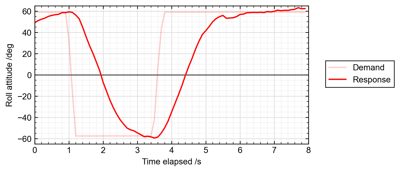 Inner loop roll controller response to step inputs
 Inner loop pitch controller response to step inputs
Initial Data
Some further flights gathered additional data for analysis, noting that the windy conditions (estimated above 7 m/s by the EK3 wind estimator) make the data not the most reliable for comparison with other logs. The pitch loop PID components show a significant integrator contribution during level flight which initially suggests an unbalanced aircraft, but the contribution is negative, indicating nose down elevator. The cause for this has not been determined.
I put the Phoenix in a 500x500 m square AUTO mission and recorded the power draw at a set airspeed of about 15 m/s. This allows direct comparison with my original set of data for the Orca as shown below, with two strong caveats: the Orca data was from a still day, not 10 m/s gusting winds, and the Phoenix has not yet had an inner or outer loop tune. The result is higher power draw for the Phoenix despite an identical powertrain, but I’m confident this number will reduce under more representative test conditions. The data as presented also suggests the 90+ minute endurance of the Orca should be met handily by the Phoenix.
 Power draw comparison between the Orca and Phoenix
I performed a couple of full power low passes in FBWA and the maximum achievable level flight airspeed is 33 m/s. A cautious stall test was performed in Manual and the aircraft had benign stall characteristics, dropping the nose below about 9 m/s.
 Speed data for a low pass at full throttle
ArduPilot System Identification
I attempted to use the System Identification feature in ArduPilot to characterise control response of the airframe with this tune. I created the custom firmware in the field to enable the feature and used the 4.8.0-dev branch at the same time. After updating SCHED_LOOP_RATE to 100 Hz and mapping the System ID activation to a spare transmitter switch, I flew 90 second straight flight paths at constant speed to first test roll and them test pitch, repeating each axis twice. Both axes were tested from 0.1 Hz to 3 Hz with a roll angle of 5 degrees and a pitch angle of 3 degrees.
Both axes exhibited well-fitting data up to about 0.7 Hz excitation, and a second-order model could be derived for responses up to this frequency. Above this, the results of the two roll test differed but the pitch responses correlated well, as shown in the bode plots.
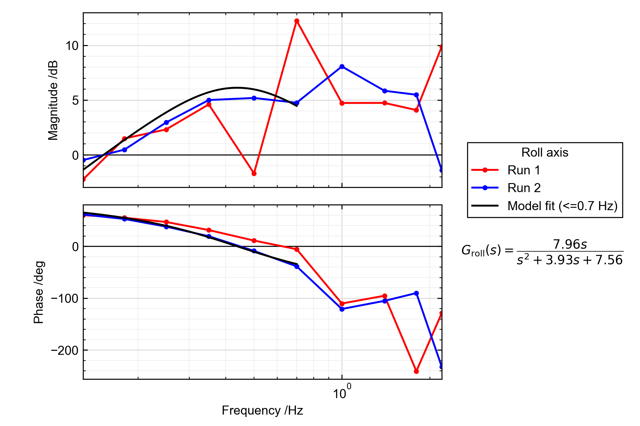 Bode plots for roll controller response
 Bode plots for pitch controller response
I validated the second order models against some of the FBWA step input response data from earlier, and the model accuracy seems surprisingly good, especially considering the model is derived from low magnitude chirps (5 degrees roll/3 degrees pitch) whereas the step input data uses the full envelope limits of ±60 degrees roll and ±30 degrees pitch, plus a number of other caveats from the model derivation.
 Validation of second order roll and pitch transfer functions against real data from FBWA step inputs
This was a bit of an experiment to see if the data was usable, I’m about at the limit of my control theory understanding for now. Once I’ve re-tuned the system, I’ll revisit this and see if I can get better correlation on the higher frequency excitations and resulting models, but these may always be unreliable due to the inherent effects of servo dynamics, coupling between pitch and roll, and changing airspeeds over the duration of the tests. Perhaps a calmer day will yield better results!
Summary
All-in-all, a very successful maiden day for the Phoenix, with a total of 1 hour 4 minutes flight time over 10 flights and zero crashes. Had the weather been better, the inner loop tune would have been a good target to have completed, but that excitement can be saved for another day. Fingers crossed it can become another reliable workhorse for my fleet!