Orca Built and Flying
Payload carrying aircraft build from kit with ArduPlane setup
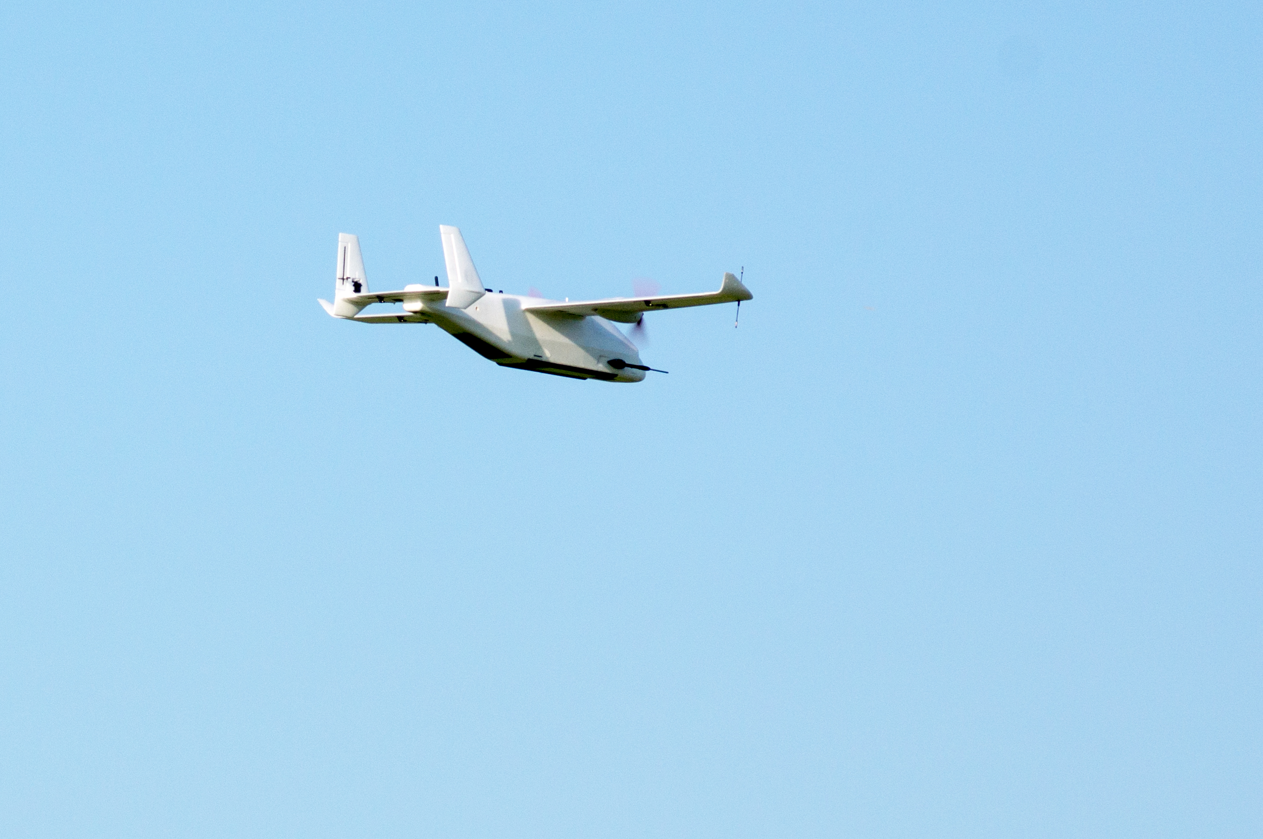
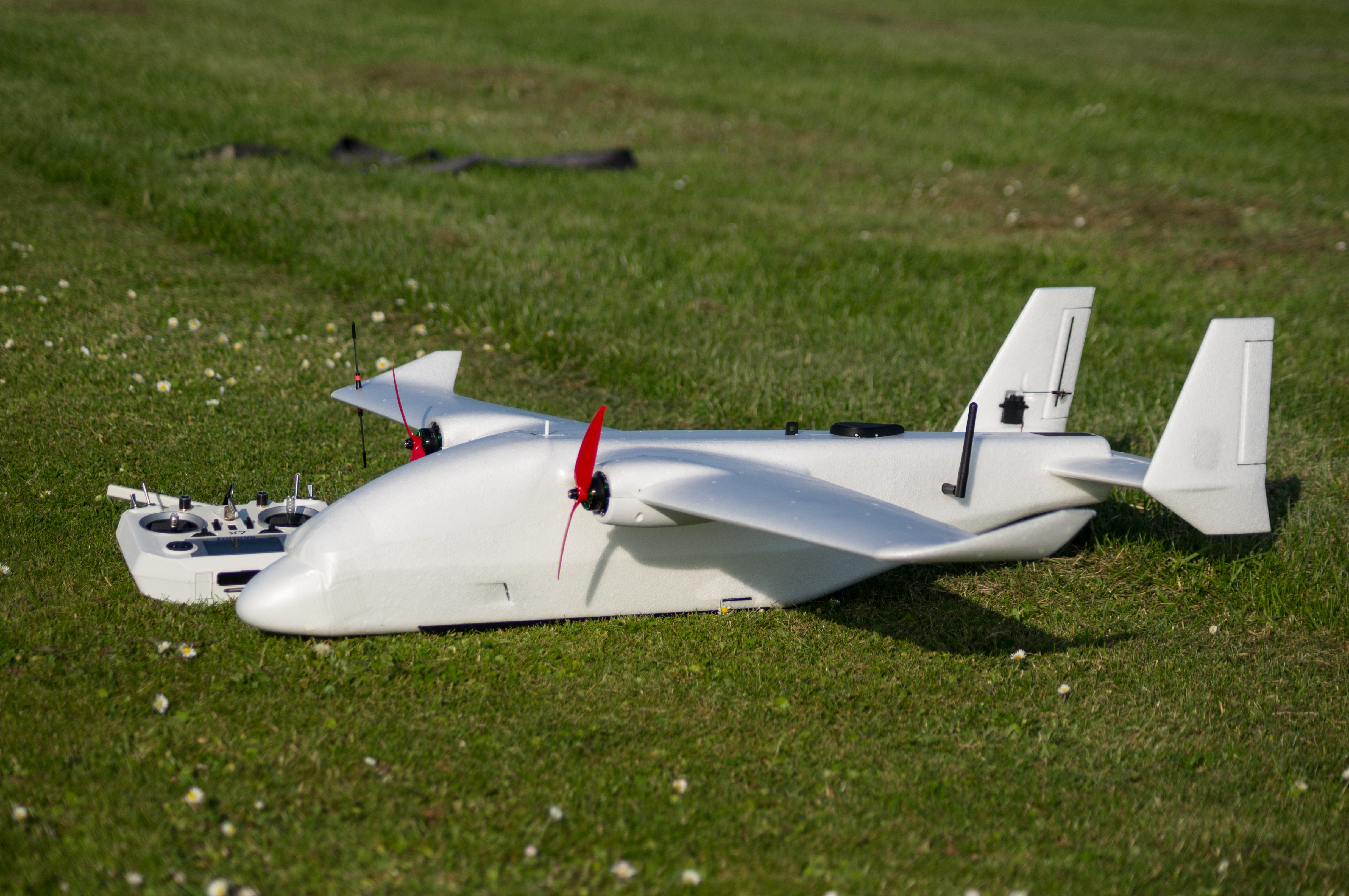
It’s been over a month since I finished the build of the AtomRC Killer Whale and did some initial flight testing and tuning. And as the full name is a bit of a mouthful, I call it the Orca.
Build
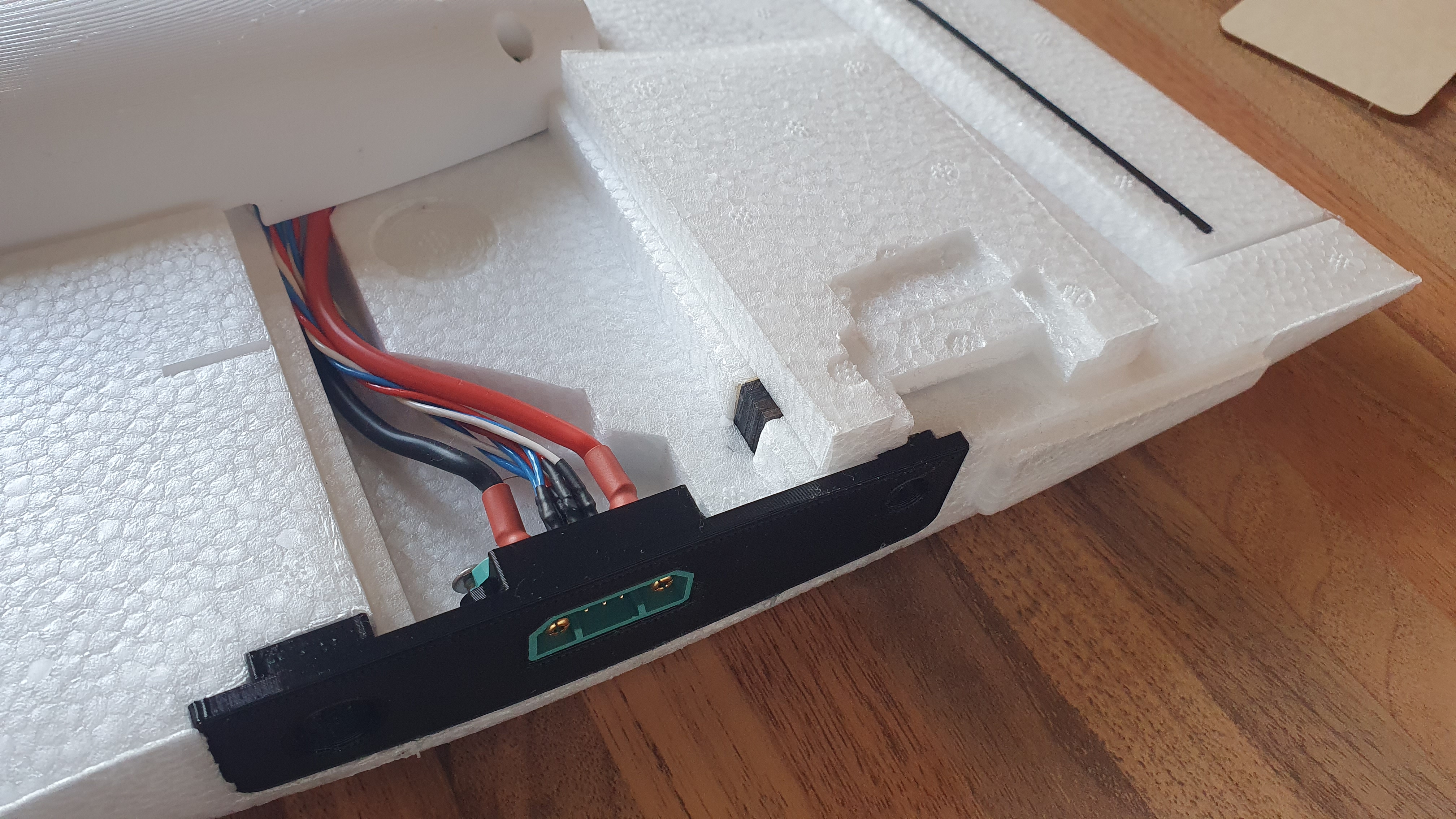
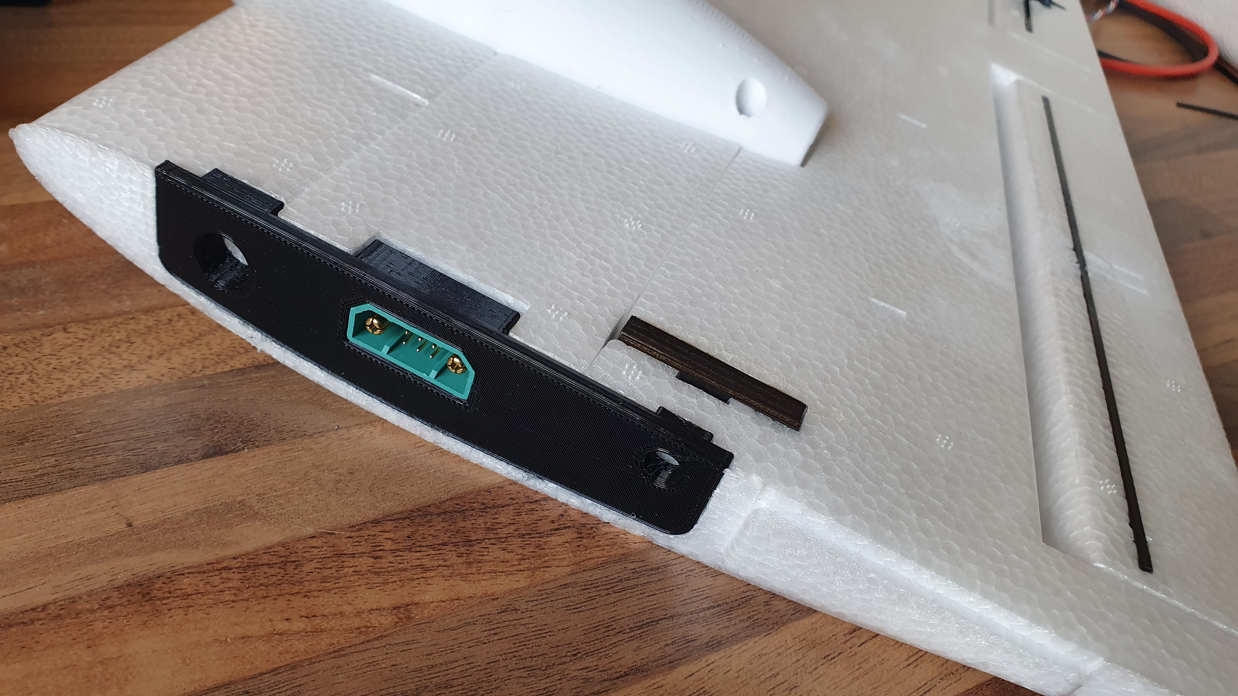
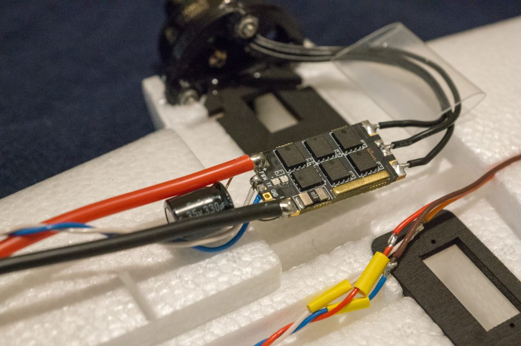
The build was quite uneventful, but I made a few modifications from stock to keep things neat and improve the assembly/disassembly for flying days. The main two modifications are a slimline motor mount and fairing, and wing root endplates to integrate JX9 connectors. The motor fairings are redesigned to be low profile since I’m not a fan of how large the stock foam fairings are. These are thin walled for the majority of the section to keep weight down, and interface to printed ESC and flap servo plates with integrated threaded inserts. The motor mount itself was also redesigned to improve airflow behind the motor to account for the loss of the large vent on the stock fairing. I chose JX9 connectors for the wing-fuselage connections, as these connectors feature 9 signal pins and 2 dedicated power pins, ideal for routing power to the ESCs and with enough pins to leave some spare for any future components that I might add to the wings.
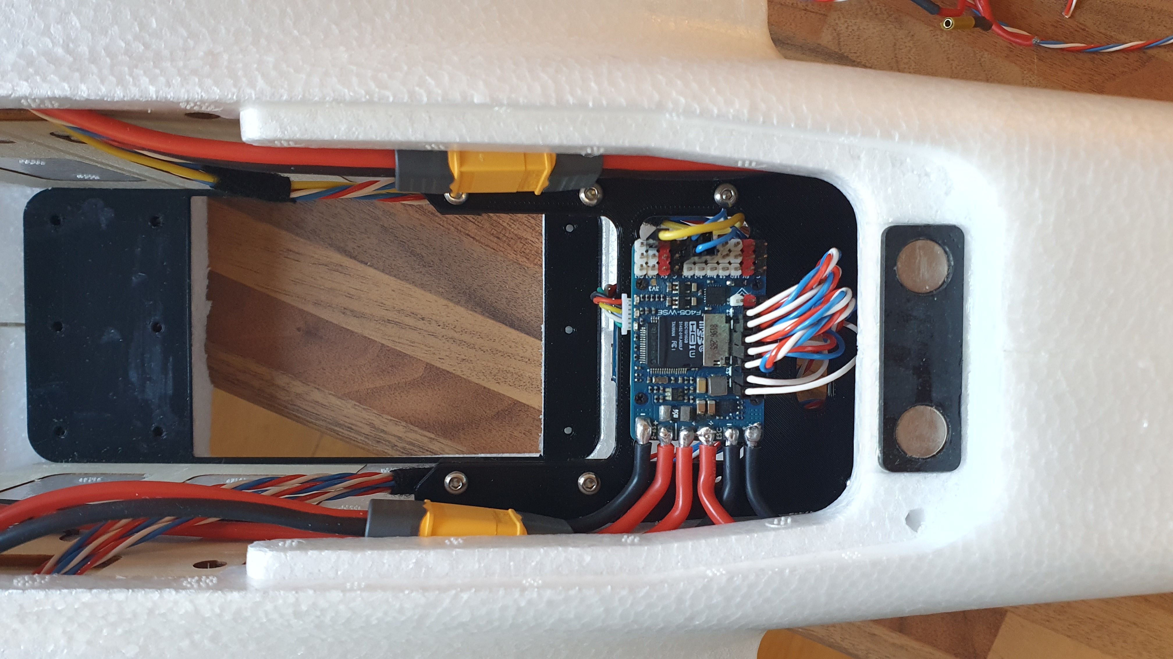
Inside the fuselage, I created a new modular tray system for both the flight electronics and payload bay. This was partly done out of necessity, since the kit arrived with the fuselage halves already glued together, meaning the stock trays couldn’t be installed! Both mounts use permanent mounts with threaded inserts, allowing for trays of custom size to be designed and mounted easily. I also cut a large hole in the bottom of the fuselage for any future payloads that might want to retract or have a view of the ground. Other minor mods include a pitot mount, skids, and using an 8-pin connector for the fuselage-tail interface. Most of these 3D printed mods I have made available in a collection on Printables for anyone who wants to use them.
Some changes were made to the system layout that was initially planned, such as removal of the VTx systems and redundant RC receiver. These aren’t necessary for what I plan to use it for but I have left the wiring in place to make adding them in the future less painful.
The electronics were fitted without any fuss. For this build, all major flight systems are transplanted from my old ASW28, including the Matek Systems F405-WSE flight controller, FrSky R9MM RC receiver on 868 MHz, GPS and airspeed sensors, and the 433 MHz telemetry module. There is space to mount future 2.4/5 or 5.8 GHz devices in the front of the fuselage or on the port wing, since the 868 MHz transceiver is on the starboard wingtip and the 433 MHz transceiver is in the rear of the fuselage. The GPS receiver is mounted on top of the fuselage above the flight controller. With this setup, frequency deconfliction between RF devices is prioritised and no two RF devices currently share the same frequency. With the small size of the aircraft, increasing separation between RF devices is not really an option!
I didn’t include flap servos but everything else followed the manual, including the default control surface throws. I’m not a fan of hand launching fixed wings, so the skids on the fuselage allow for easy ground launches. Finished, the Orca weighs 1.25 kg without batteries. I run it from 2x 4S 3300 mAh LiPos which weigh just over 300 g each, bringing the all-up weight to 1.89 kg. Now, time to fly!
Flight Testing
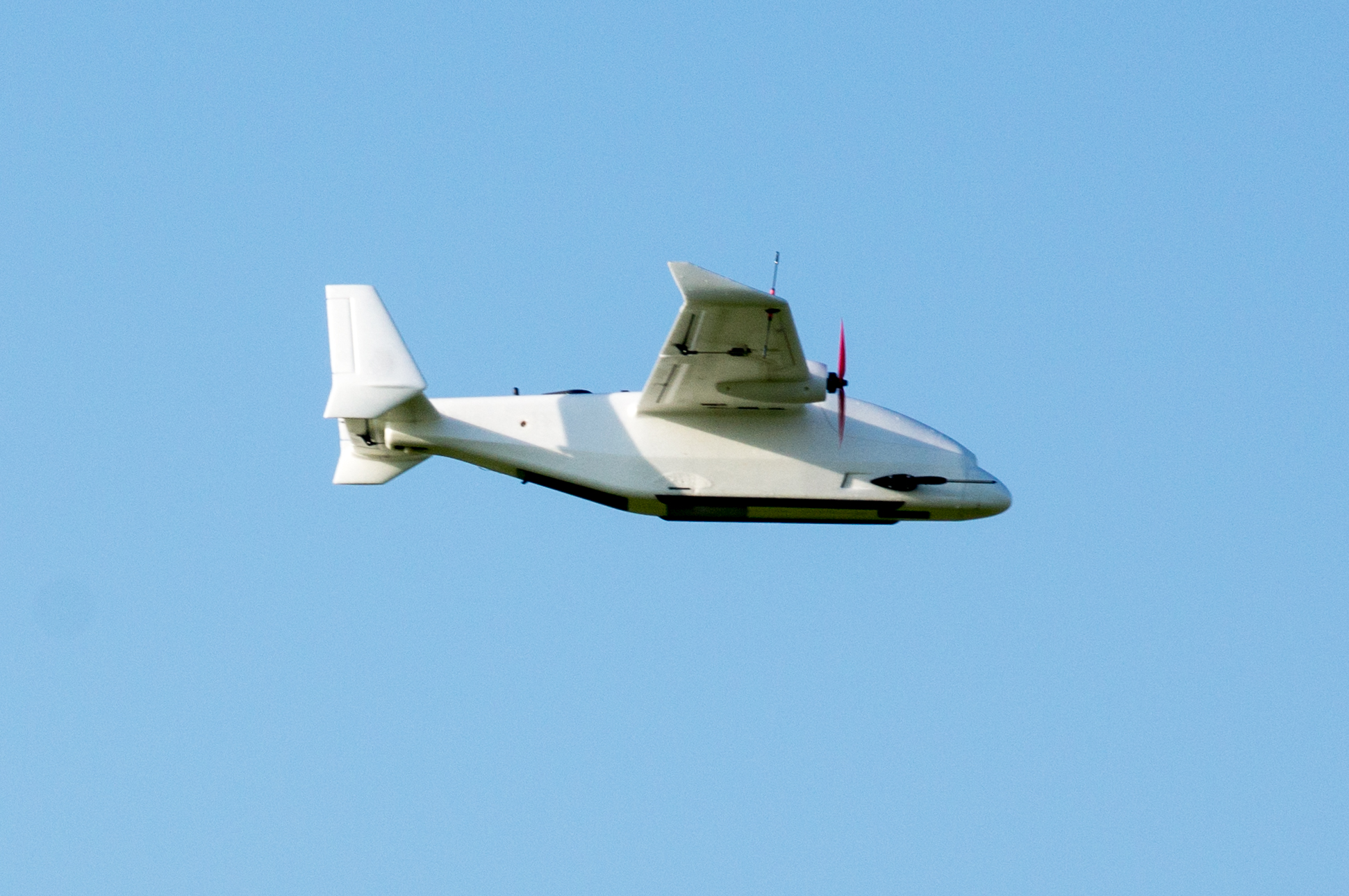
The weather at the beginning of June was perfect for some flight testing and tuning, so I gathered some data. Once tuned, the aircraft is fantastic to fly! It slows to below 10 m/s easily, has very benign stall characteristics without a hint of tip stall, and the skids make take off and landing a breeze. The propulsion configuration is a pair of 2306 1400kV motors and 7” props, running on 45A Holybro Tekko ESCs with BlHeli32 firmware. The stock suggestion is to use triblades, but I also bought biblades and compared performance as long endurance efficiency is more important than thrust or speed for me. Specifically, I tested 7x4x3 and 7x4.2x2 Gemfan propellers, contra-rotating with the descending blade inboard on both sides.
 Prop efficiency testing at 15 m/s cruise speed
Above, you can see the results of some efficiency testing for the two propeller configurations. The aircraft flew a repeating series of waypoints in Auto at 15 m/s cruise speed for 20 minutes. The raw data is shown in the background, with a 30-second simple moving average overlaid on top to show more clearly how the average power draw differs. The biblades achieve an efficiency approximately 30% better than the triblades, with a mean efficiency of 0.92 Wh/km or 60.6 mAh/km. If you aren’t familiar with these units, they allow easy extrapolation into an ultimate range of the aircraft, since batteries are measured with a Wh or mAh capacity, so simply dividing the battery capacity by the efficiency yields the theoretical maximum range. For the combined 6600 mAh 4S battery, this is 109 km, although there are obviously considerations to be made such as battery depth of discharge, weight of payloads, and weather conditions which reduce this figure in practice.
| Prop Blades | Efficiency [Wh/km] | Efficiency [mAh/km] | | :———— | :————— | ——: | | 2 | 0.92 | 60.6 | | 3 | 1.29 | 85.8 | Final results for the prop comparison test
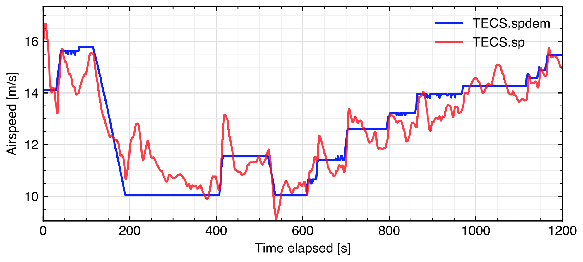
Next was investigating efficiency as a function of airspeed. Flying took place on a dead calm evening, with winds below 1 m/s for the duration. I flew in FBWB to maintain altitude and allow the throttle stick to control the TECS speed demand (TECS.spdem), and varied the airspeed between 10 m/s (the FBW min airspeed) and 16 m/s. The figure below shows the aircraft response (TECS.sp, the actual TECS speed) to the commanded speed. Although not perfect, the aircraft stays within 1 m/s of the commanded speed for a large majority of the time once the command reaches steady state. This response is without any further tuning to the TECS airspeed control loops other than the stock Ardupilot setup.
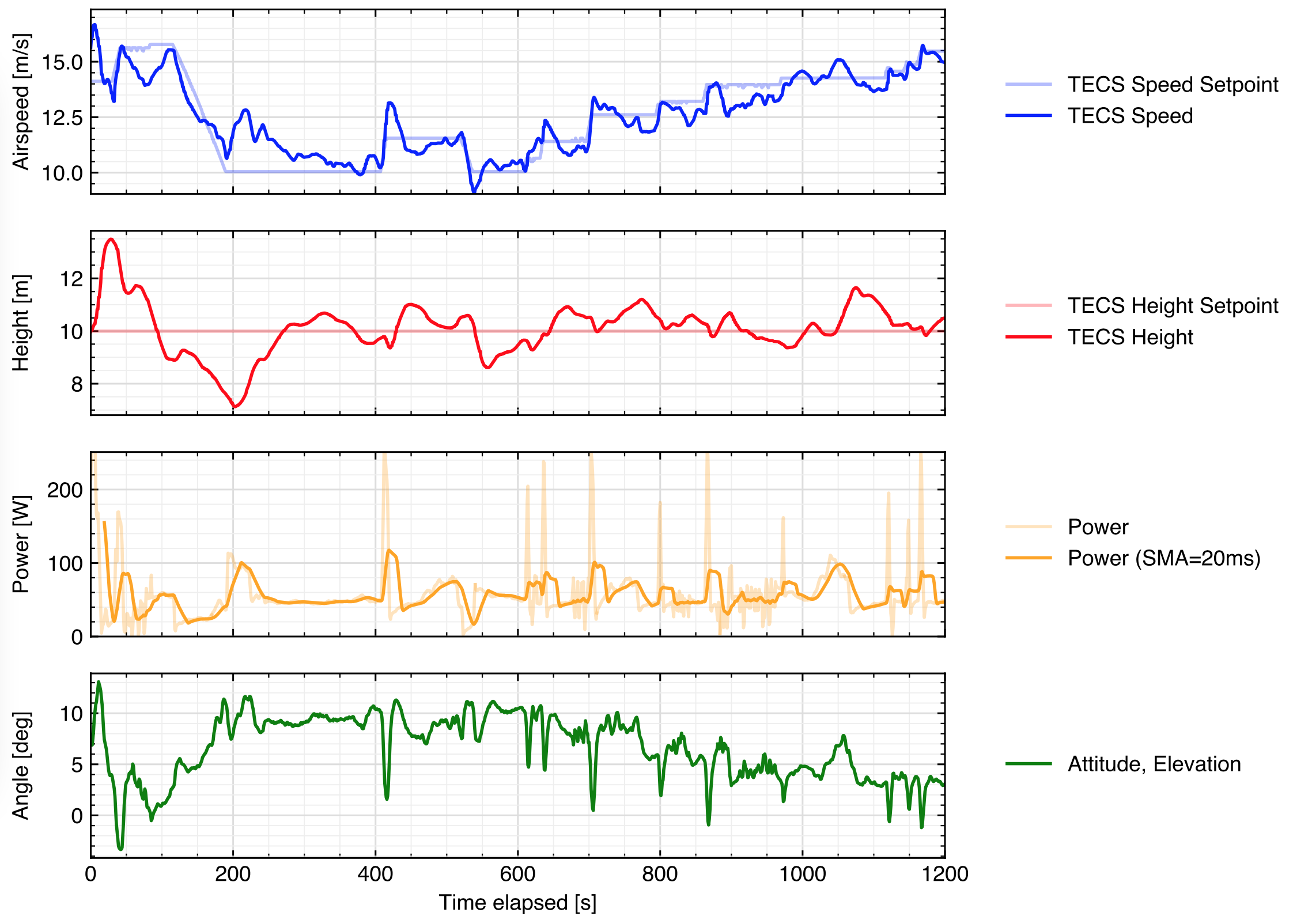
For this period, several other metrics were recorded to help determine the best cruise speed. The figure below shows these metrics plotted as simultaneous timeseries, with the airspeed response provided first for reference. The height response is very reasonable with little tuning - after the initial pertubations settle, caused by the large change in airspeed command, the height follows the setpoint within 1 metre for the vast majority of the test, and never diverges as far as 2 metres.
Each airspeed was commanded for a duration of approximately 100 seconds, and as shown in the latter half of the data, the power draw difference between the airspeeds was very small, indiscernible in practice from the presented data. What is shown, however, is that high spikes in input power are less frequent as airspeed command increases. This is a result of the low throttle command requested by the autopilot causing the ESCs problems due to their inability to drive very low rotational speeds. This causes large current spikes as the motor begins to spin after being stationary, which could be avoided by better calibrating the ESC input PWM endpoints or choosing an ESC with better low-load startup performance. Or, as is seen for the higher airspeeds, by commanding a motor speed above this region so that the ESC does not have to start from stationary. After this test, the minimum throttle was also set to 5% to prevent the motors from ever coming to a full stop when the aircraft is armed. Lastly, the elevation angle (nose pointing angle above the horizon) is shown to trend down towards zero, i.e. level flight, as the airspeed command increases. This is expected as the TECS controllers balance the throttle and pitch to maintain airspeed. From this data, a cruise airspeed of 13 m/s or greater should be used to minimise elevation angle for any future payloads which may be sensitive to attitude, as well as allow faster traversal speed with minimal impact on power draw - therefore providing greater maximum range for the same maximum endurance time.
Nav Tuning
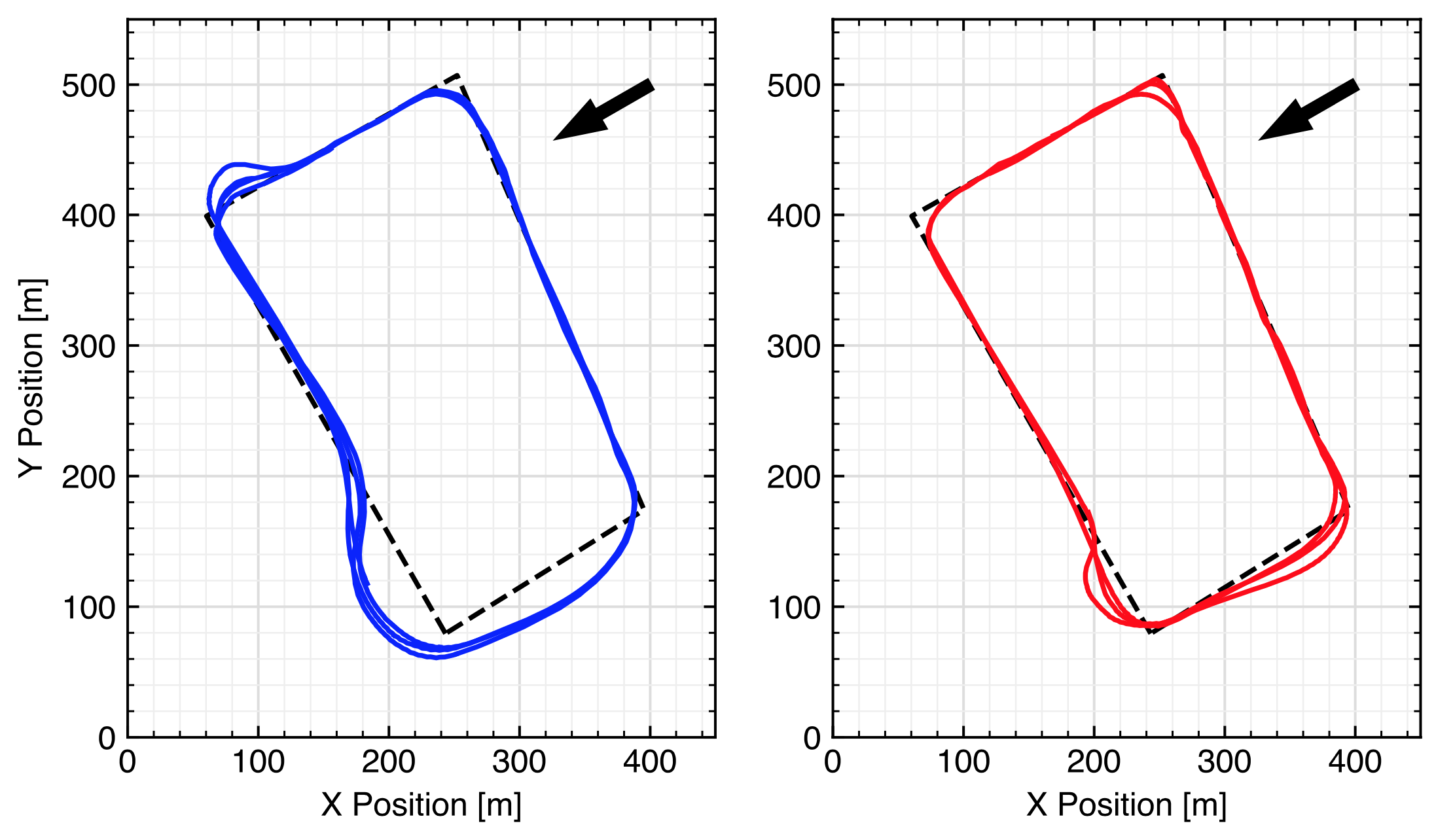 Nav tuning for clockwise circuits, showing track (a) before tune, and (b) after tune. Note the arrow showing wind direction and the dashed line indicating the layout of the waypoints
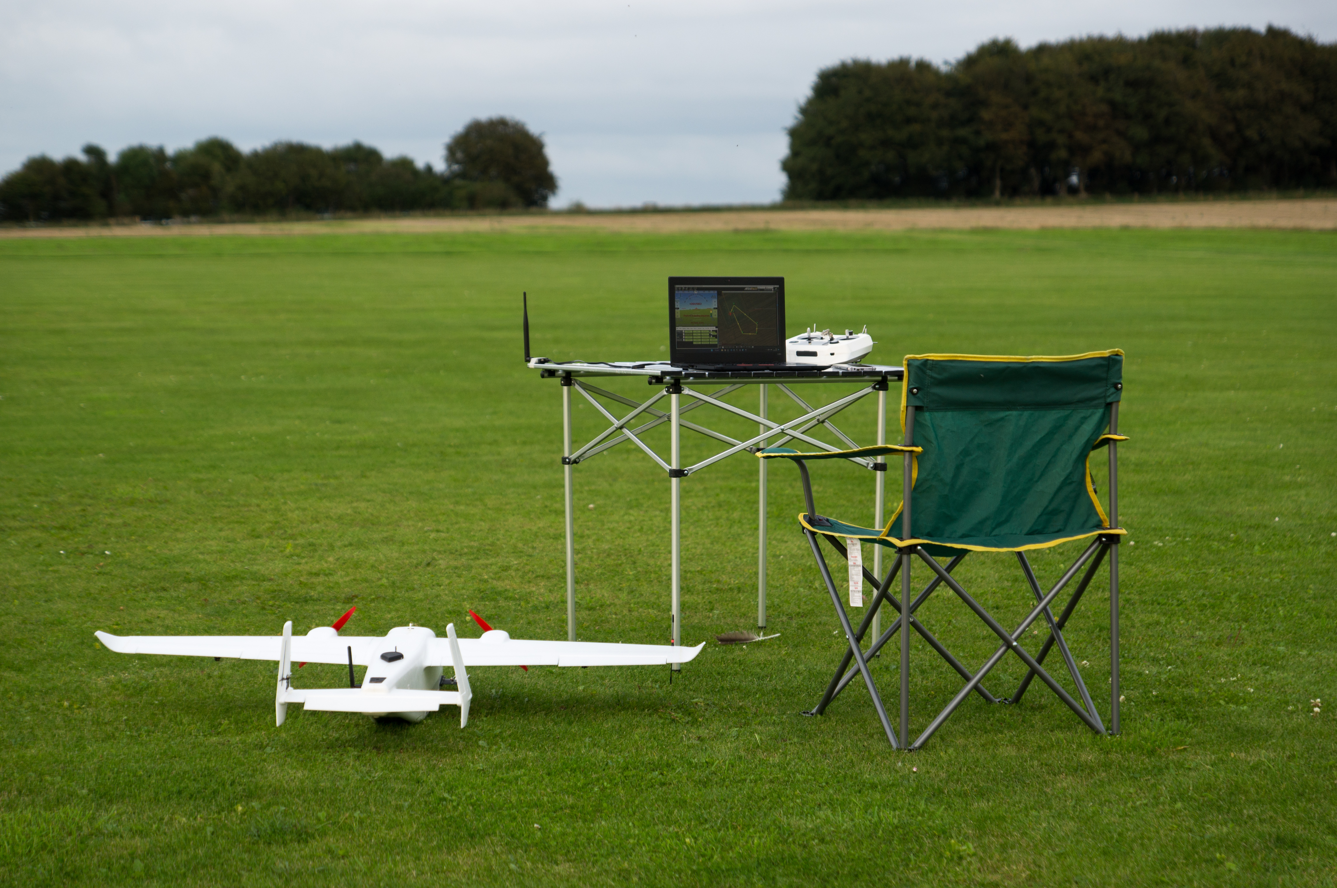
The navigation controllers and parameters were tuned on another day, where the winds were steady and in excess of 10 m/s, which made for an interesting test environment for the little Orca with a cruise speed of 13 m/s! Significant gains were made, as seen in the figures above, and although I was concerned that it may have overtuned the nav controllers for calmer days, subsequent flights showed this wasn’t the case. In addition to setting the WP_RADIUS parameter to 35 m, I finished with the following NAVL1 controller gains, if you need to tune your own Orca:
| Parameter | Value |
|---|---|
| NAVL1_PERIOD | 12 |
| NAV1L_DAMPING | 0.8 |
| NAV1L_XTRACK_I | 0.04 |
| NAV1L_LIM_BANK | 60 |
