Flying the Oblique Wing
Building and flying a 3D printed oblique wing demonstrator
At the start of the year I was inspired by Mustard’s excellent video on the oblique wing concept and wanted to give it a go for myself with an RC scale model. I took this on as a quick side project for a bit of fun, and so I chose a very limited number of requirements to meet, which were:
- The wing must be able to rotate in the air on command
- Use my newly tuned LW-PLA filament
- Use as many repurposed parts from old projects as possible
The design process was very quickly completed, with a basic wing sized based on a typical high wing foam trainer, adding a bit of taper to extend the span. The ailerons were deliberately sized to have a larger than normal chord length and a shorter than normal span, as well as being placed as close as reasonably practicable to the wing tip. These design features were an effort to ensure that when the wing is fully swept, the control surfaces can maintain sufficient roll authority. The tail was oversized by 50% to ensure stability. The only other key design choice was the use of the flat bottomed Clark Y airfoil for the wing, which would provide a large, flat interface to constrain the wing at all sweep angles. This also required the top of the fuselage to be flat which caused the somewhat unusual cross-section of the fuselage.
The wing is constrained by a single M6 bolt and actuated by a large 20 kg servo motor. This servo is intended for RC car steering linkages, and is intentionally oversized for this application - it is critical that this servo does not fail during flight as that could lead to a freely spinning wing!
The build process went very smoothly and I found plenty of areas that could be improved the next time I create a fully 3D printed model. Instead of using custom internal structure as is common with 3D printed models, I elected to save effort by using a low percentage infill for the majority of the structure and adding modifiers in PrusaSlicer to increase the infill density in key structural areas. The image of the wing root part below shows an example, where 5% cubic infill is used throughout the part but the area directly surrounding the main wing spar is reinforced with 20% infill. This method worked very well and avoided the need for a physical spar in the outer wing panels, instead relying only on a volume of higher density infill. It eliminates time from the design process, only adding a few seconds to the slicing process and, in the wing root panel example below, only an 8% weight penalty. The fuselage was sliced with a more conventional profile to maintain strength, but in hindsight this was probably unnecessary. All parts were printed with a single perimeter.
 Slicer example showing the tailored infill density around the spar
Once assembled, I installed and setup the flight controller which for this project was a Speedybee F405 Wing. With ArduPilot flashed, the setup was straightforward as with any model, and I chose to control the wing rotation servo by direct RC passthrough. The wing rotation servo was also powered by a dedicated BEC rather than the flight controller itself, to prevent any failure of the servo from impacting other flight critical systems.
The maiden flight wasn’t a complete success! The handling characteristics were very poor and this was attributed to the undersized tail boom causing the tail to deflect under aerodynamic load, resulting in very unpredictable pitch response. You can see the result of this when activating fly by wire in the downwind leg after take-off, where the nose immediately pitches down and could not be recovered except by switching to manual. The landing was hard but only resulted in a stripped wing rotation servo horn, so I upgraded to a more substantial tail boom for the next flight.
Along with a larger tail boom, I modified the tail to have an adjustable tailplane angle of up to 2.5 degrees pitch down and secured by setscrews, which I used for the remaining flights. The second flight was a much more successful attempt and I was able to test the swing wing for the first time.
Now happy with the performance, I added a bit of colour to the airframe and attached my FPV camera on the tail to capture some in-flight video. I also added in a spare GPS receiver and set it up for auto take-off. Initially, I made the oversight of not checking the CG before flying which caused an immediate crash! After reprinting the fuselage and waiting almost a month for a weather window I was able to get out and record the final in flight videos of the oblique wing in action.
I was interested in looking at the flight log data to see how the system responded to the pitch/roll coupling experienced by the larger NASA oblique wing prototypes, but sadly the log files were corrupted. Qualitatively, the use of ArduPilot’s fly by wire significantly reduced any noticeable control effects from the swing wing, with flight control remaining very easy regardless of the wing sweep angle. The tricky part is to maintain awareness of the orientation of the model, as having the wing sweep both fore and aft of the pivot is much more disorienting than I expected!
I created a longer-form video which shows some of the manufacturing process and additional video of the flights.
All of the aims were met including the reuse of many old components:
- Motor, propeller, and tail servos from my crashed Durafly Tundra
- ESC from my autonomous boat project
- Wing servos and main spar from my crashed Volantex ASW28
- Tail boom from an old foamboard wing
- RC receiver from a 3 inch racing quad which I’d upgraded to ELRS
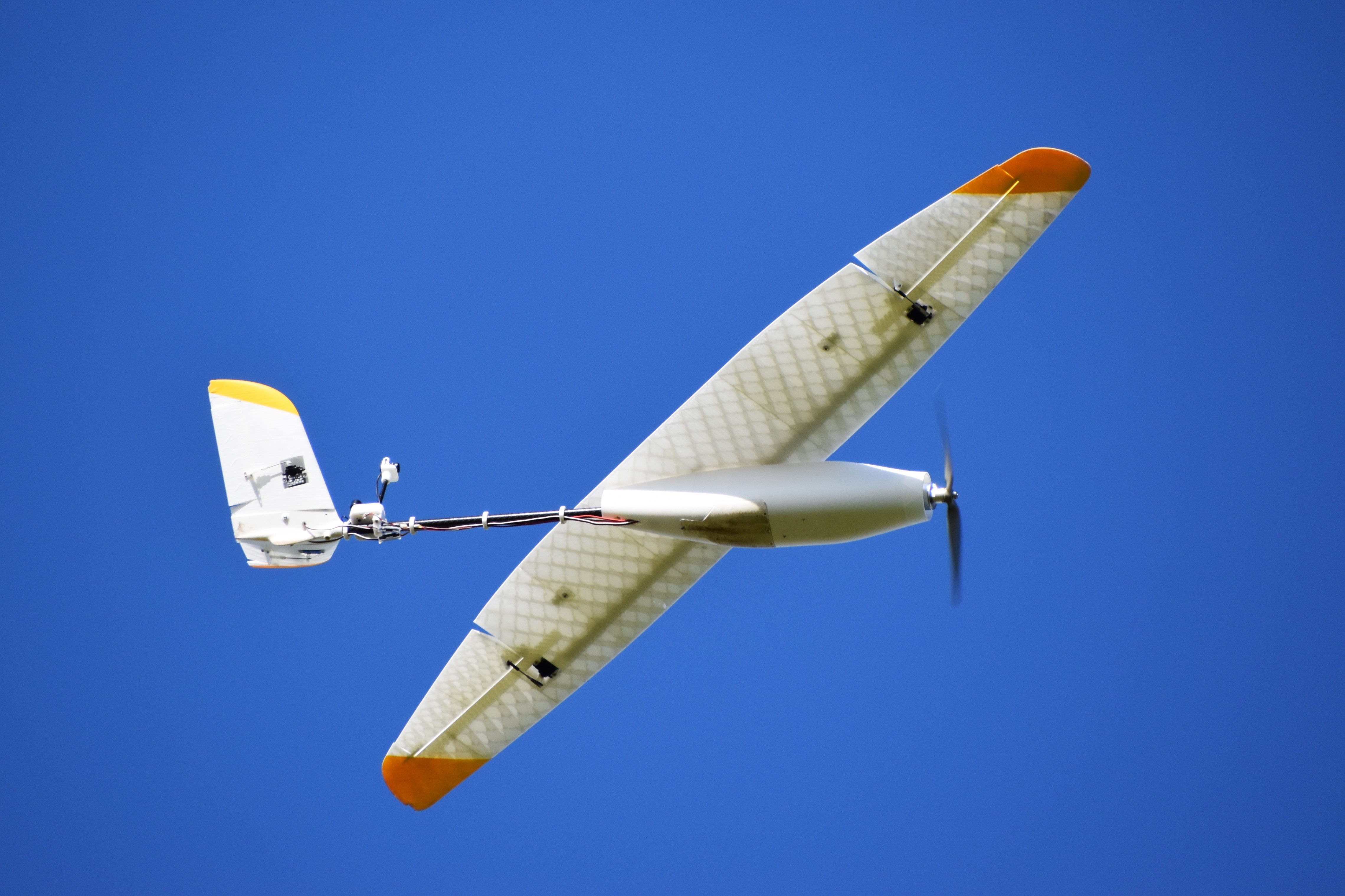
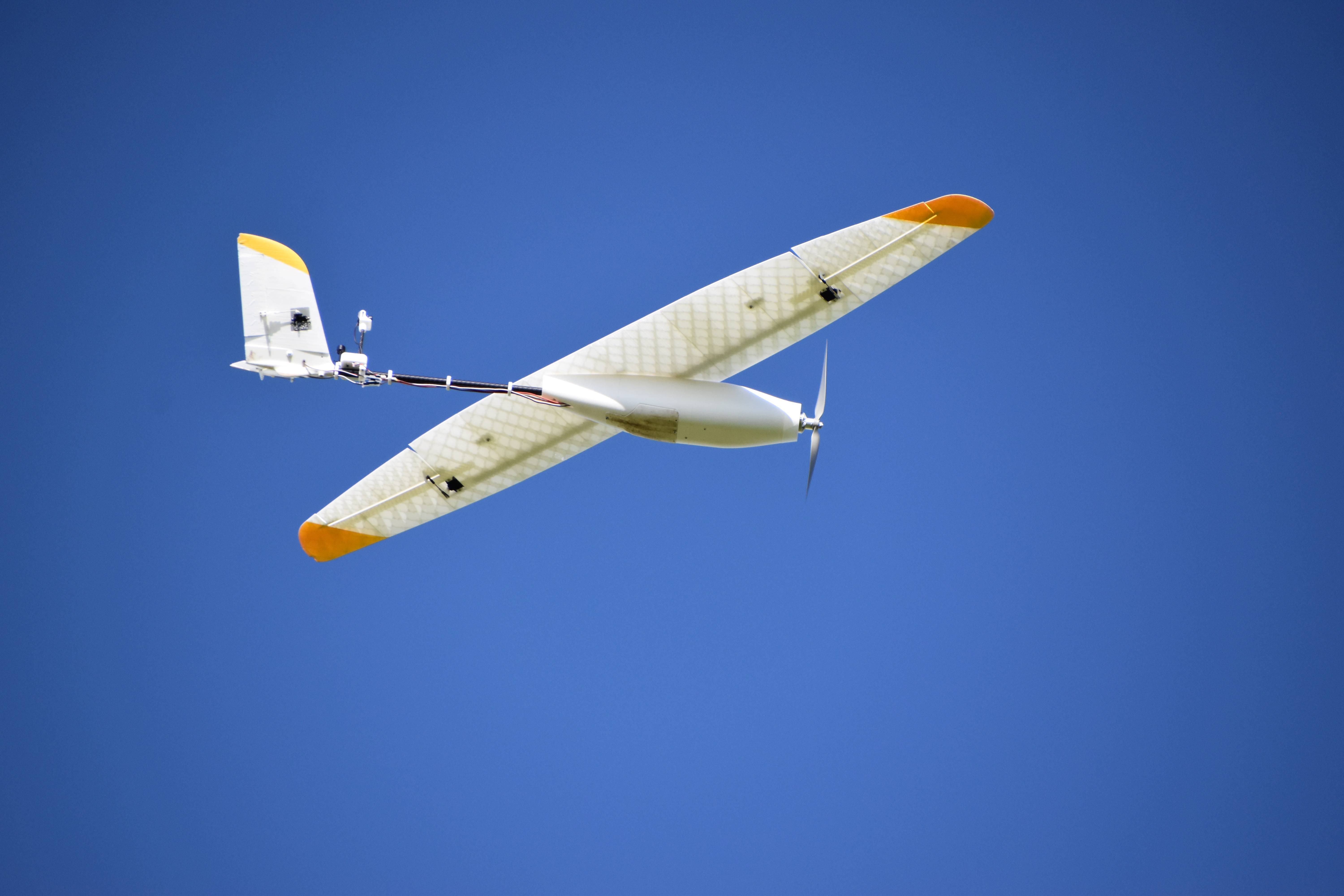
Finally, a few shots of the aircraft in flight, thanks to some of my fellow aeromodellers at the flying site. I particularly like the backlight allowing the internal structure of the wing to be visible!

